3D Printing Guidelines
by 3D Hubs
Step 1. Understanding the importance of STL export resolution
The STL file format uses a series of linked triangles to recreate the surface geometry of a solid model. When increasing the resolution (and size) of your file, more triangles are placed on the surface of the model.
Step 2. Choosing the right resolution when exporting
You can change the resolution by altering the tolerance in your CAD package. Each CAD package has a different way of specifying this but most of them include chord height and angle control.
The chord height is the maximum distance from the surface of the original design and the surface of the design in STL format. The smaller the chord height, the smaller the facets and the more accurately the curvature of the surface is represented.
Printability
The most important thing to keep in mind when designing for 3D printing is the fact that the process will be turning a digital design into something real. In a design environment, there are no laws of physics to adhere to such as gravity or the expanding/shrinking of the material you want to print in.
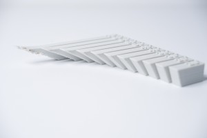
Overhang
An overhang is where the printed layer of material is only partially supported by the layer below or not supported at all. All printer technologies are based on an additive process, with the layer about to be printed requiring a layer below it to adhere to (with the exceptions of SLS and Binder Jetting). There are limits that printers can print up to, 45 degrees for FDM, beyond which support material is needed to support overhangs and allow them to be printed accurately.
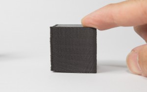
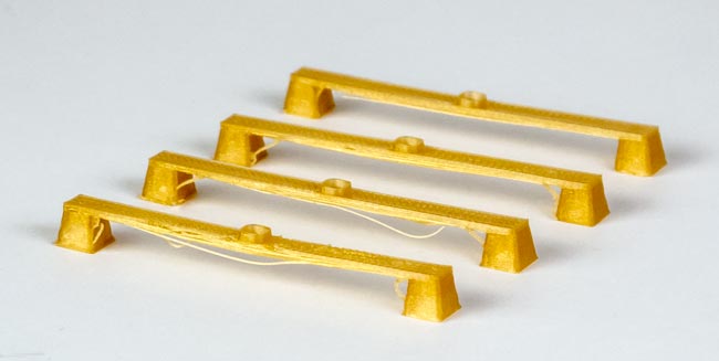
Warping
Something often easily overlooked is the fact that in order to 3D print, 3D printing techniques such as SLS and FDM, rely on heating up the material to over 200 ℃ to either melt or sinter material. The heating up and cooling down of material can cause some warping of the 3D print.
Long, flat surfaces can be especially prone to warping. Warping can typically be avoided by using correct machine calibration and having adequate surface adhesion between your part and the print bed. Your Hub will be able to offer more advice on design techniques that can be used to minimize the likelihood of warping occurring.
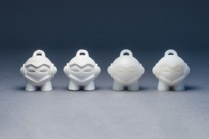
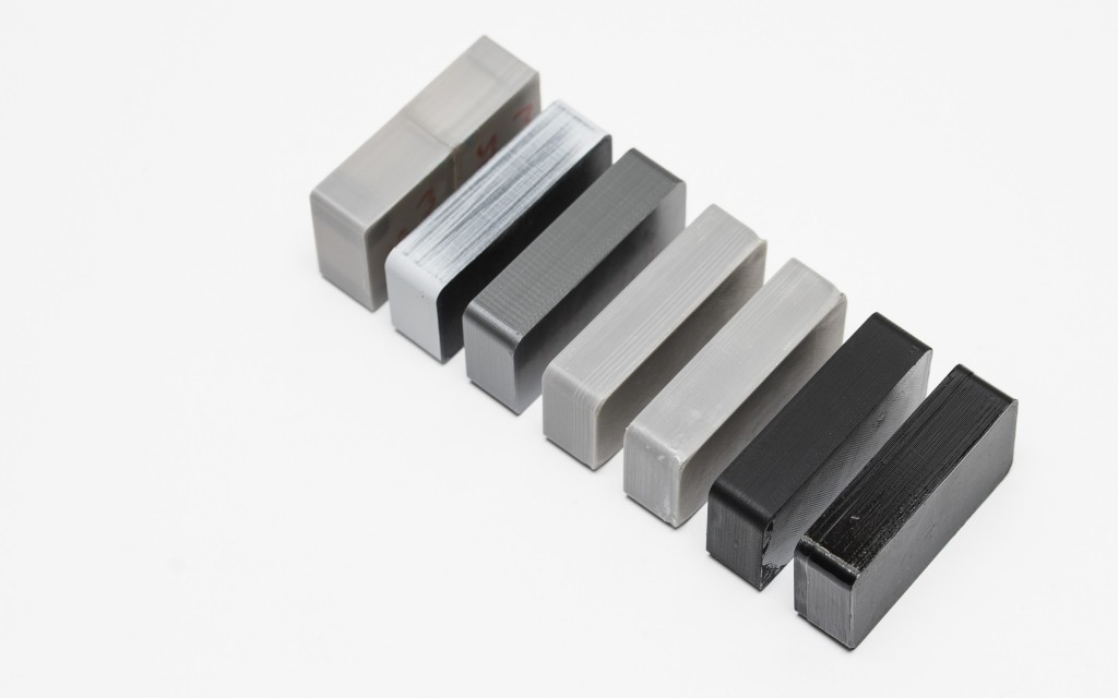
Details
When you’re creating a design with intricate details, it’s important to know whether or not the details will even show up in the final print. FDM will generally struggle to clearly show features below 0.8mm, whereas SLA and Polyjet is more suited for applications where these smaller features are important (down to 0.2mm).
The process and materials used will have an impact on the speed and cost of your print, so determining whether smaller details are critical to the design is an important design decision.
Supports in 3D Printing
As 3D printed parts are built layer by layer, a previous layer to build upon is required. Depending on the specific 3D printing technology and the complexity of the 3D model, this can mean that a 3D print requires support structures.
When considering what technology to print a 3D model with, it is important to consider support structures and how they may affect the final result. Support structures will have an impact on surface finish as they require post-processing work to remove, resulting in blemishes or surface roughness.
This article discusses supports, how supports are implemented for each 3D printing technology, and how the use of supports can impact the design decision making process.
FDM support structures
Fused Deposition Modeling (FDM) extrudes a melted filament onto a build surface along a predetermined path. As the material is extruded, it cools, forming a solid surface providing the foundation for the next layer of material to be built upon. This is repeated layer by layer until the object is completed.
When is FDM support material needed?
With FDM printing, each layer is printed as a set of heated filament threads which adhere to the threads below and around it. Each thread is printed slightly offset from its previous layer. This allows a model to be built up to angles of 45°, allowing prints to expand beyond its previous layer’s width. When a feature is printed with an overhang beyond 45°, it can sag and requires support material beneath it to hold it up.

The downside of FDM support material
One of the limitations of using support in FDM printing is that post-processing is always required, resulting in marks or damage to the surface in contact with the support. Another issue is that layers printed upon support will be less perfect as the support will be slightly less stationary than the solid layers. Support can also be difficult to remove from small, intricate features without breaking the model.
Furthermore, support requires additional printing material and therefore incurs additional costs. The support also needs removal, creating more work for the 3D printing service provider which can also increase the total cost of the print job.
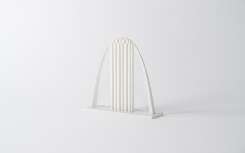
How much support is needed for my FDM print?
The arch example below requires only a limited amount of support placed in the correct location to allow it to be printed accurately.
Dissolvable support
On finely tuned printers with two print heads, the support material can be printed with a dissolvable material that does not tear away from the part but instead dissolves away in a chemical solution that does not affect the main material of the printed model. This will result in a better surface finish where the support is in contact with the main material but can be an expensive and a time consuming solution. An example of this is the Ultimaker 3 machine which utilizes support printed in PVA that is easily dissolved post print.
SLA and DLP support structures
Stereolithography (SLA) and Digital Light Processing (DLP) create 3D printed objects from a liquid (photopolymer) resin by using a light source to solidify the liquid material. Depending on the exact printer type, this means that the model is either pulled out of a vat containing liquid material as it is solidified by a light source through a translucent window at the bottom (bottom-up), or it is submerged into the liquid as the top layer is treated by a light source from the top (top-down).

Bridging
Bridging in FDM occurs when the printer is required to print between two supports or anchor points. Because there is no support offered for the initial layer being printed (there is nothing to build upon) and it is required to “bridge” a gap, the material will tend to sag. Bridges occur most often in horizontal axis holes found in the walls of objects or in the top layer (or roof) of hollow parts.
Post Processing for FDM parts
FDM is best suited for cost effective prototypes produced with short lead time. Parts are generally not functional and ideal for applications where form or fit checks are needed. Because of this, FDM parts often depend on aesthetics or appearance making post processing an important stage in the production of FDM parts.
Sanding
Tool kit
-
150, 220, 400, 600, 1000, and 2000 grit sandpaper
-
Tack cloth
-
Toothbrush
-
Soap
-
Face mask
Process: After supports are removed or dissolved, sanding can be done to smooth the part and remove any obvious blemishes, such as blobs or support marks. The starting grit of sandpaper depends on the layer height and print quality; for layer heights of 200 microns and lower, or prints without blemishes, sanding can be started with 150 grit. If obvious blemishes are present, or the object was printed at a layer height of 300 microns or higher, start sanding with 100 grit.
Sanding should proceed up to 2000 grit, following common sanding graduations (one approach is to go from 220 grit, to 400 grit, to 600 grit, to 1000 grit and finally 2000 grit). It is recommended to wet sand the print from start to finish, to prevent friction and heat build up from damaging the part and keep the sandpaper clean. The print should be cleaned with a toothbrush and soapy water, then a tack cloth, between sanding gradations as well to prevent dust buildup and “caking”. FDM parts can be sanded up to 5000 grit to achieve and smooth, shiny finish.
Vapor Smoothing

Tool kit
-
Tack cloth
-
Solvent-safe sealable container
-
Solvent
-
Paper towels
-
Aluminum foil (or other solvent-proof material)
-
Face mask & chemical-resistant gloves